

Hey there! As a supplier of 400G QSFP112 SR4 transceivers, I often get asked about how to test the performance of these little tech wonders. So, I thought I'd share some insights and tips on this topic.
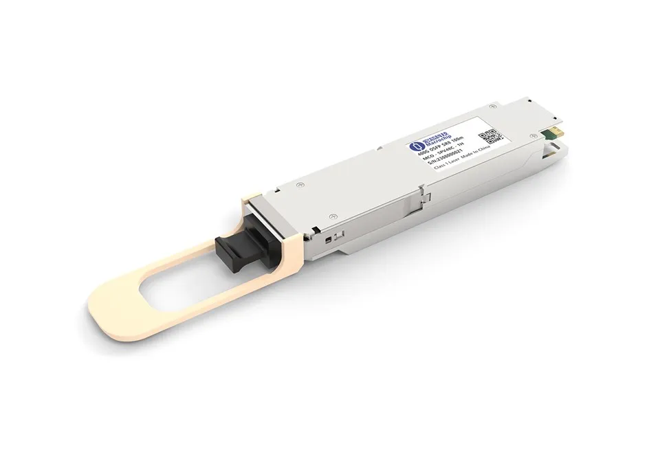
First off, let's quickly understand what 400G QSFP112 SR4 is. It's a high - speed optical transceiver module designed for short - reach applications in data centers. With a data rate of 400 gigabits per second, it's a crucial component for modern high - performance networks.
1. Prerequisites for Testing
Before we start testing, we need to gather the right tools and set up the environment. You'll need a test platform that can support the 400G data rate. This usually includes a high - speed network switch or a test chassis that can interface with the 400G QSFP112 SR4 module. Also, make sure you have the appropriate optical fibers. For SR4, multimode fibers (MMF) are typically used, usually OM3 or OM4.
You'll also need some test instruments. A bit error rate tester (BERT) is essential. It can generate and analyze high - speed data streams to check for errors. An optical time - domain reflectometer (OTDR) can be used to measure the loss and integrity of the optical fiber. And a power meter will help you measure the optical power of the transceiver.
2. Physical Inspection
The first step in testing is a simple physical inspection. Check the module for any visible damage, like scratches on the optical interface or bent pins. Make sure the connector is clean. A dirty connector can cause significant signal loss and errors. You can use a fiber optic cleaner to clean the connector. Just be gentle, as the optical interface is very delicate.

3. Insertion and Power - On
Once you've done the physical inspection, carefully insert the 400G QSFP112 SR4 module into the appropriate slot on the test platform. Make sure it's properly seated. Then, power on the test platform and the module. You should see some indicator lights on the module and the platform. These lights can give you an initial indication of whether the module is powered on correctly.
4. Optical Power Testing
Use the power meter to measure the transmit and receive optical power of the 400G QSFP112 SR4 module. The optical power should be within the specified range. If the transmit power is too low, it could mean there's a problem with the laser in the module. If the receive power is out of range, it could be due to fiber loss or a problem with the receiver in the module.
To measure the transmit power, connect the power meter to the transmit port of the module using an appropriate optical patch cord. Record the power reading. Then, connect the power meter to the receive port of the module (after connecting the fiber from the transmit port of another module or a test source) and measure the receive power. Compare these readings with the module's datasheet.
5. Bit Error Rate (BER) Testing
The BER test is one of the most important tests for any high - speed transceiver. Use the BERT to generate a high - speed data stream and send it through the 400G QSFP112 SR4 module. The BERT will then analyze the received data stream for errors.
Set up the BERT with the appropriate data rate and pattern. For 400G QSFP112 SR4, the data rate is 400 Gbps. You can use a pseudorandom binary sequence (PRBS) pattern, which is a common test pattern. Run the test for a sufficient amount of time, usually a few minutes or more, depending on the required accuracy.
The BER should be extremely low, typically on the order of 10^ - 12 or lower. If the BER is higher than the specified value, it could indicate problems such as signal distortion, interference, or a faulty module.
6. Eye Diagram Testing
An eye diagram is a graphical representation of the signal quality of a high - speed data stream. You can use an oscilloscope to capture the eye diagram of the 400G QSFP112 SR4 module.
Connect the oscilloscope to the electrical output of the module. The eye diagram should show a clear "eye" opening. A wide and clear eye opening indicates good signal quality, while a narrow or distorted eye opening could mean there are problems with the signal, such as jitter or inter - symbol interference.
7. Comparing with Other Modules
It can also be helpful to compare the performance of the 400G QSFP112 SR4 module with other similar modules. For example, you can compare it with Single Mode Optical Module or QSFP DD DR4 or OSFP Optical Transceiver. This can give you a better understanding of how your module performs in the market and if there are any areas where it can be improved.
8. Temperature and Environmental Testing
High - speed transceivers can be affected by temperature and environmental conditions. You can test the performance of the 400G QSFP112 SR4 module under different temperature conditions. Use a temperature chamber to control the temperature. Run the BER and optical power tests at different temperatures, such as 0°C, 25°C, and 70°C.
Also, consider testing the module in different humidity conditions. High humidity can cause corrosion and other problems. Make sure the module can perform reliably under a wide range of environmental conditions.
Conclusion
Testing the performance of 400G QSFP112 SR4 modules is a comprehensive process that requires the right tools and techniques. By following these steps, you can ensure that your modules meet the high - quality standards required for modern data center applications.
If you're in the market for high - quality 400G QSFP112 SR4 modules, we're here to help. Our modules are rigorously tested to ensure optimal performance. Whether you're building a new data center or upgrading an existing one, we can provide the right solutions for your needs. Feel free to reach out to us for more information and to discuss your procurement requirements. We're always happy to have a chat and find the best solutions for you.
References
- "Optical Transceiver Technology Handbook"
- Manufacturer's datasheets for 400G QSFP112 SR4 modules